∷Construction Process:
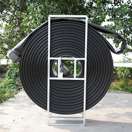
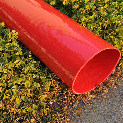
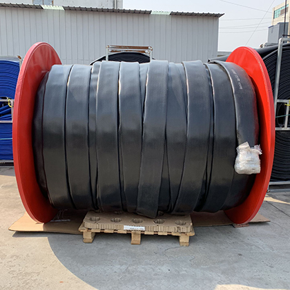
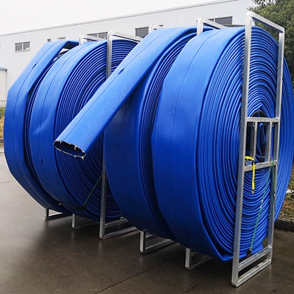
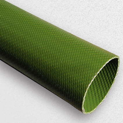
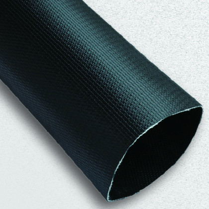
FFPP™ PVC plastic pipe has been widely used in the rehabilitation project of gravity pipe(<DN900), including rain water pipeline and drainage.

ü Prior to inspection, the pipeline is cleaned using a high pressure water jet to remove any debris in the pipeline.;
ü Identify any conditions in the pipeline that could impede or prevent the proper installation of the liner.
ü Provide a record of the pre‐lined condition of the pipe;
ü Accurately record the position of all service connections.
The host pipe shall be cleaned in accordance with SPECIFICATION FOR SEWER LINE CLEANING as provided by the National Association of Sewer Service Companies (NASSCO).:
Roots:The pipeline shall be cleared of obstructions such as roots, solids, offset joints, protruding service connections or collapsed pipe that may prevent pipe liner installation. If inspection reveals an obstruction that cannot be removed by conventional sewer cleaning equipment then a point repair excavation shall be made to uncover and remove or repair the obstruction.
High levels of groundwater infiltration:High levels of groundwater infiltration into the host pipe, that will affect the successful installation of the liner shall be remediated by either chemical grouting or point repair prior to lining as approved by the Engineer.
Offset Joints: Offset or dropped joints of more than one inch of the inside pipe diameter can cause ribs to form in the liner, similar to a collapsed pipe. To avoid ribs in the liner, sections of pipeline containing offset or dropped joints should be point repaired prior to lining.
Protruding taps: Service taps that protrude into the pipeline more than 12.5% or 2.5cm should be cut off using a chain flail or remotely controlled grinder.
l Equipment Setup
l Heat the Liner
l Liner Insertion
l Liner Forming
A.Equipment Setup
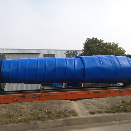
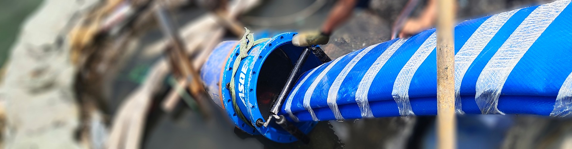
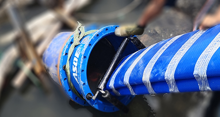
Stage a steam boiler apparatus, flow‐through plug, and the coiled liner at the upstream structure (i.e., headwall, manhole, drop inlet, etc.). Stage a winch, flow‐through plug and exhaust manifold at the downstream structure. Use a jet apparatus to run the winch cable from the downstream structure to the upstream structure.
B.Heat the Liner
Drill holes through the end of the liner pipe and connect the winch cable. Enclose or cover the coiled liner and heat with steam at approximately 88°C. Heating time will vary depending on ambient temperature, altitude and steam quality. The heated liner must be pliable enough to be pulled into the host pipe with as little resistance as possible.
C. Liner Insertion
The liner pipe shall be inserted into the sewer through existing manholes, without modification of the manholes. Insertion of the liner into the host pipe will be accomplished by pulling the liner into the host pipe by means of a steel cable strung through the host pipe from a winch located at the downstream manhole. The end of the liner shall be prepared for attachment to the cable in accordance with the manufacturers instructions. The connection between the pulling cable and the prepared end of the liner shall be a swivel device to prevent twisting of the liner as it is pulled through the host pipe. The heated liner coil shall be placed in such a manner as to prevent damage to the liner as it is pulled through the manhole and into the host pipe.
D.Liner Forming
After the liner pipe has been inserted and plugged at the upstream station, allow the liner pipe relax for approximately five (5) minutes. The liner pipe relaxation is particularly important if the liner pipe has been stretched during the insertion process, and may require more than five (5) minutes in those cases.
Insert a flow‐through plug into the upstream end of the liner (the upstream end may be reheated in order to soften the material enough to insert the plug). Leave a “window" of pipe liner between the opening of the host pipe and the end of the plug to allow for observation of the liner as it is processed. Attach the steam hose to the upstream plug, and apply steam at approximately 100°C through the liner. Heat and relax the liner until movement at the downstream station has stopped.
Cover the downstream end of the liner with a tarp or similar cover to allow the steam flow to soften the material enough to insert the downstream flow‐through plug. Connect the downstream flow‐through plug to an exhaust manifold, and apply a small amount of back pressure (approximately 0.04 bar) to the liner system. Do NOT close the exhaust plug valve. The steam temperature and pressure are monitored and controlled at the upstream and downstream process stations.
Heating time is determined by the length and wall thickness of the liner. Additional heating time may be added by the installer if warranted by conditions within the host pipe. As the liner is thoroughly heated, internal pressure is slightly increased to cause the liner to conform tightly to the interior of the host pipe. 0.2 bar to 0.35 bar of backpressure should be sufficient to form the liner in the host pipe. At the end of the heating time, switch from steam to compressed air. Maintain internal pressure until the exhaust air temperature has reached a predetermined temperature (usually 40° C).
Water may be induced into the compressed air during the cooling process to reduce the cooling time. Cooling shall be deemed complete when the temperature of the exhaust air or air water mixture has remained constantly below 40ºC for a minimum of 20 minutes.
Upon completion, and before acceptance of the work, the Contractor will inspect the rehabilitated pipeline using a CCTV camera with a pan and tilt head. The inspection shall be recorded on either VHS or DVD after the liner has been cooled.
Ensure that the liner has formed properly and that there are no defects in the liner. The Operator will stop the camera at each lateral reinstatement and using the pan and tilt feature record and catalog each of the service connection cuts.
Use pipe robot to reconnect all active service connections:
In most cases required service connections will be reconnected using closed circuit television and remotely controlled cutters;
All existing service connections shall be reinstated either by remotely controlled robotic device or by excavation;
Use a brush‐ or rasp‐type bit to make service connection holes;
The opening shall be smooth and conform to the inside shape and size of the original connection.
Service reconnections shall be smooth and circular in nature as observed by a pan and tilt TV camera. The hole shall be a maximum of 105% and a minimum of 90% of the service pipe diameter.

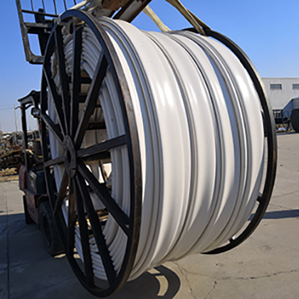
Asoe could provide professional FFPP™ solution, including the PVC alloy liner, installation container(which contains all tools for installation), project plan and engineering service.